This guide describes how Vulcan’s calculators derive the fabric input properties written into HEM:FHS-compatible JSON (building elements attached to each zone). The calculators do not by themselves reproduce HEM’s full dynamic fabric / node heat balance; they supply the thermal fields the engine consumes alongside the rest of the dwelling model. The published standards remain authoritative; this page records what the software computes and which input properties are written.
Property names follow the HEM FHS JSON Schema (e.g. input_fhs.schema.json) — in particular the BuildingElement discriminated union and its type-specific branches.
Where these controls appear in Vulcan
In Geometry, select a fabric element and use the Editor.
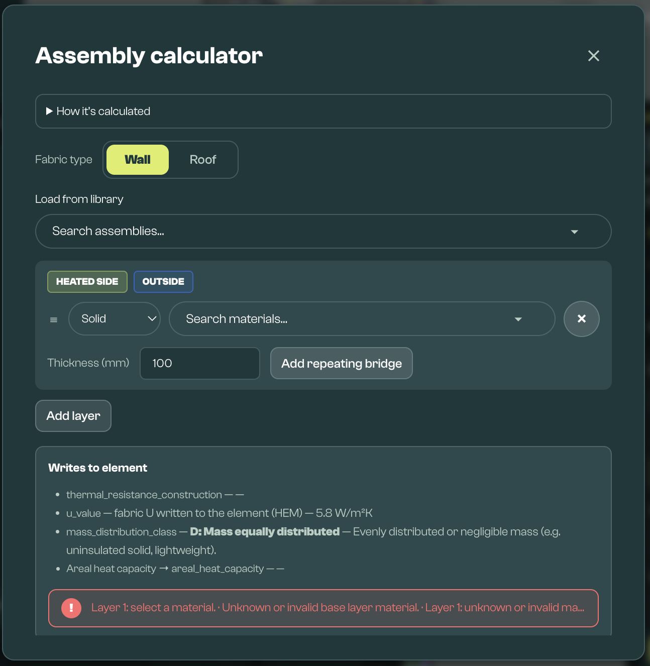
Assembly picker: Builds up an opaque, party, adjacent, roof, wall, or floor construction from layers and writes the calculated fabric values back to the selected element.
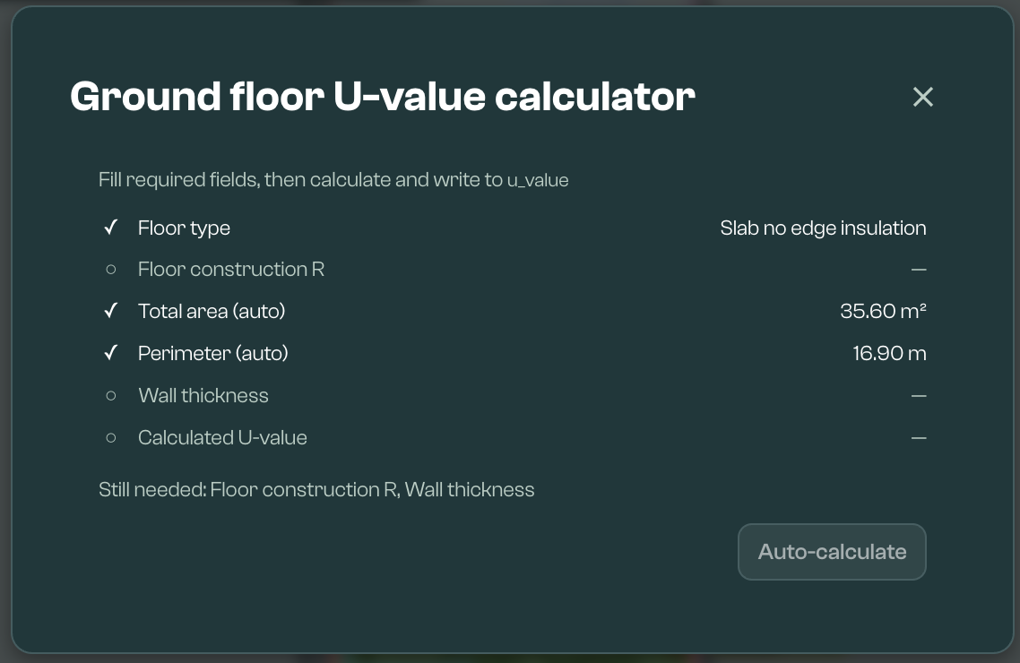
Ground U-value tools: Help calculate ground-floor U-value inputs from floor area, perimeter, floor type, wall thickness, and relevant insulation or ventilation fields.
Thermal resistance of unheated space tool: Helps calculate R_u for an element next to an unheated garage, loft, stairwell, corridor, or similar space.
After applying calculator values, save the model and review Geometry validation before using the model for calculation.
1. Assembly calculator (layered opaque fabric)
Applies to fabric elements edited through the layered construction editor — typically BuildingElementOpaque, BuildingElementPartyWall, BuildingElementAdjacentConditionedSpace, and BuildingElementGround (see §1.11). For most opaque-like fabric type values, Vulcan’s HEM:FHS export path normalises the element to use either thermal_resistance_construction or u_value (see §4.1). BuildingElementGround is different: it requires thermal_resistance_floor_construction and u_value among other fields; when enough ground inputs are present, Vulcan recalculates ground u_value from the steady-state ground path after resistance inputs change (see §5).
1.1 Standards and scope
- Construction resistance uses BS EN ISO 6946, combined method: arithmetic mean of lower and upper construction-resistance limits.
- Internal surface resistance Rsi uses the same radiative and convective coefficients as BS EN ISO 13789 Table 8 as implemented in HEM (resistance = 1 / (hri + hci)).
- External resistance Rse in this calculator is not always 1 / (hce + hre); see §1.2.
1.2 Surface resistances used in U preview
Rsi from element pitch (degrees from horizontal), using the same pitch bands as for cavity heat-flow direction:
| Band | pitch | hci (W/(m²·K)) | Rsi (m²·K/W) |
|---|---|---|---|
| Horizontal | 60° to 120° inclusive | 2.5 | 1 / 7.63 ≈ 0.131 |
| Upwards | below 60° | 5.0 | 1 / 10.13 ≈ 0.0987 |
| Downwards | above 120° | 0.7 | 1 / 5.83 ≈ 0.1715 |
Fixed hri = 5.13 W/(m²·K).
Rse:
- Default 0.04 m²·K/W when no well ventilated cavity terminates the modelled stack.
- With exactly one well ventilated cavity as the outer boundary, layers outside that cavity are omitted and Rse is taken from BR 443–style tabulated values for that cavity: high surface emissivity → 0.13 (horizontal heat flow) or 0.10 (upwards); low emissivity → 0.29 (horizontal) or 0.17 (upwards). Downward heat flow with that cavity type is rejected by the calculator (error state).
- For
Suspended_floorground-floor assemblies, the underfloor void is used to split the build-up into floor deck and ground-side insulation. The deck resistance is then assessed from the layers above the void; the void itself is not treated as the outer ventilated cavity for that deck calculation, so the normal 0.04 m²·K/W external resistance applies to the deck step.
For U:
U = 1 / (Rsi + R′′T,mean + Rse)
where R′′T,mean is the combined-method construction resistance (no films).
Some auxiliary tooling uses Rse = 1/(20 + 4.14) ≈ 0.0414 m²·K/W when inferring construction R from a declared U; that value can differ slightly from the 0.04 default above.
Round-trip drift: The assembly preview uses the conventional 0.04 m²·K/W external surface resistance (and the film model above) unless a ventilated-cavity outer boundary applies. U → R inference uses the HEM-style external h combination that yields ≈ 0.0414 m²·K/W. Small differences after recompute are expected, not a numerical bug.
1.3 Homogeneous layer resistance
R = d / λ (d thickness in m, λ thermal conductivity in W/(m·K)).
1.4 Repeating thermal bridges within one layer
Clear field and bridge strips are parallel. With clear-field fraction fclear = max(0, 1 − Σ fi), clear resistance Rclear, and each bridge i with fraction fi and resistance Ri:
G = fclear / Rclear + Σ (fi / Ri), Req = 1 / G
Bridge fractions must not exceed 100% of the layer area (small numerical tolerance).
1.5 Cavities
Effective cavity resistance depends on cavity type, ventilation (unventilated / well ventilated), emissivity, gap, and heat-flow direction derived from pitch. Explicit unventilated cavities use the product’s bundled BR 443-style resistance conventions; the calculator does not expose the full ISO 6946 air-layer table.
1.6 ISO 6946 combined construction resistance
- Lower limit R′′T,lower: parallel paths within each bridged layer, then layers in series.
- Upper limit R′′T,upper: bridged layers share aligned in-plane fraction vectors; paths through columns in series, columns combined in parallel.
R′′T,mean = (R′′T,lower + R′′T,upper) / 2
Repeated bridges across layers: For the upper limit, every bridged solid layer must use the same in-plane fraction vector as every other bridged layer (aligned framing). If fractions differ between layers, the assembly calculator reports an error — misaligned stud / batten patterns are outside the simplified combined method in this tool and need a separate modelling approach or detailed calculation.
1.7 When Apply is blocked
- Invalid layer ordering or cavity rules (e.g. cavity against heated space only, adjacent cavities, outermost layer a cavity, more than one well ventilated cavity).
- R′′T,upper / R′′T,lower strictly greater than 1.5 (ISO 6946 §6.7.2.1 — simplified combined method not applicable).
BuildingElementGroundwithfloor_typeSuspended_floorbut no single well ventilated underfloor void cavity in the stack (the calculator requires this to mark the void).- Other resolution errors (series stack, void geometry, or outer ventilated-cavity / heat-flow rejection).
1.8 Calculation limits (unsupported or needs detailed modelling)
Treat these as outside the simplified assembly calculator unless methodology explicitly allows a correction:
- Continuous metal penetrations through insulation (e.g. steel rails, continuous brackets, large-area conducting paths): BR 443 / ISO 6946 scope excludes or restricts the simplified method where insulation is penetrated by metal (other than assessed discrete fixings). The repeated-bridge model is intended for discrete timbers / similar; it is not an automatic substitute for continuous steel or aluminium systems — use a numerical / certified U-value where required.
- Upper / lower ratio > 1.5: blocked (§1.7); needs a detailed route.
- Non-aligned repeated bridges across layers: blocked by fraction alignment checks (§1.6).
- Bespoke cavity or specialist build-ups not covered by the editor’s cavity rules.
1.9 Areal heat capacity and mass_distribution_class
Areal heat capacity (before mapping to schema areal_heat_capacity) is the sum over solid layers of thickness × volumetric heat capacity (from each material’s density and specific heat). Air cavities are omitted — they contribute no thermal mass in this calculator. Layers with repeating thermal bridges use the same clear-field and bridge fractions as for thermal resistance, with capacities combined in parallel in-plane (area-weighted).
mass_distribution_class is chosen by a layer-stack heuristic consistent with HEM-TP-07 (Calculating thermal mass within the Home Energy Model): insulation is detected from material category or thermal conductivity λ < 0.05 W/(m·K); heavy thermal mass uses defined material categories (including masonry, concrete, screeds, tiles, bedding, and specified gypsum/plasterboard/plaster-dab cases) and the inside → outside order of layers relative to insulation bands. The result is mapped to the FHS MassDistributionClass enum strings (e.g. mass concentrated internal, external, divided, equally distributed, or mid-construction). Unusual builds may still need assessor judgement per TP-07.
Party-wall and dwelling-side half-fabric modes apply the same half-thickness convention to the summed areal capacity as to construction resistance.
Vulcan derives two separate thermal-mass inputs: areal_heat_capacity describes the magnitude of effective heat capacity (layer-derived J/(m²·K) before any schema-facing mapping). mass_distribution_class describes where mass sits through the construction (internal / external / divided / mid / equally distributed — the FHS MassDistributionClass strings), independent of that magnitude.
For HEM:FHS export / compliance snapshots, when the profile requires a discrete thermal-mass magnitude rather than a free numeric value, the product maps the calculated areal heat capacity to one of the five schema nominal capacities — 50 000, 75 000, 110 000, 175 000, 250 000 J/(m²·K) — choosing the nearest nominal (labels Very light through Very heavy). That mapping applies only to areal_heat_capacity; it does not replace mass_distribution_class, which remains from the layer heuristic above. Working copies may retain intermediate numeric detail in product-specific metadata where enabled.
1.10 Values written to the element (schema fields)
Apply runs only if a mass distribution class can be assigned from the layer stack (mass_distribution_class and areal_heat_capacity per schema).
Opaque, party, and adjacent fabric (not ground): Vulcan computes both thermal_resistance_construction (combined-method mean R, rounded to two decimal places, after any party-half adjustment) and the corresponding u_value. The displayed / exported u_value is then derived from that rounded construction R plus films and rounded to two significant figures, unless ISO 6946 Annex F installation corrections are active — then the Annex F-corrected U is used (and need not round-trip from R). A working element may temporarily hold both R and U in extra_json after Apply; see §4 for how export picks a single authoritative field for opaque-like types.
BuildingElementGround: Apply writes thermal_resistance_floor_construction, and for Suspended_floor with a void split also thermal_resist_insul and height_upper_surface where derived. Use the Ground floor U-value calculator to calculate and write u_value once the required ground inputs are complete. For Suspended_floor with deck / ground-insulation split, Annex F corrections are not applied in the assembly step.
BuildingElementPartyWall always uses the dwelling-side half of the layered construction. BuildingElementAdjacentConditionedSpace is only halved when it is intentionally modelled as party half-fabric. In those cases, construction resistance and areal heat capacity use the dwelling-side half. Asymmetric separating constructions (different linings, voids, or insulation each side) may not behave like a simple geometric half unless the stack is explicitly the dwelling-side build-up. For adjacent conditioned fabric, the calculated fabric properties describe the element’s construction only; HEM assumes no fabric heat loss across boundaries to adjacent heated spaces (aligned with the published HEM overview for heated adjacency). The values here remain fabric inputs within the broader zone model, not a standalone heat-loss path to outdoors.
1.11 BuildingElementGround in the assembly calculator
floor_typeother thanSuspended_floor: the full layer stack is used for ISO 6946;thermal_resistance_floor_constructionis written from the combined mean R of that stack.floor_typeSuspended_floor: Apply is allowed only when the stack contains exactly one well ventilated cavity marking the underfloor void. Layers above the void define deck resistance (thermal_resistance_floor_construction); layers below definethermal_resist_insul(thermal resistance of insulation on the base of the void). Combined-method limits used for audit displays refer to the deck stack only when split.- Do not add soil or subgrade as explicit solid layers in the ground-floor assembly. The ground path is handled by the ISO 13370 calculation, and adding soil layers to
thermal_resistance_floor_constructionwould double-count ground resistance.
2. Ground-floor U calculator (steady-state ground-floor helper)
Uses BuildingElementGround fields.
Vulcan’s ground-floor U helper implements steady-state slab / suspended / basement U using ISO 13370-style expressions to populate u_value and related inputs — it is not a claim of byte-for-byte parity with every periodic / edge case in HEM’s full ISO 52016 / ISO 13370 treatment inside the engine. Periodic ground behaviour and any additional HEM-internal detail are handled in the HEM run from the JSON you supply.
Benchmark note: Vulcan’s helper follows the product’s steady-state ground-floor implementation. Because ISO 13370 ground paths are sensitive to equivalent-thickness handling, treat this helper as something to validate against reference cases for your workflows — not as a standalone replacement for the full ground boundary / fabric heat-balance treatment described in HEM technical documentation (e.g. fabric heat-loss methodology papers).
Ground elements also require psi_wall_floor_junc in the HEM FHS input. Linear floor–wall junction loss (ψ) is not folded into the area U in these formulas; ISO 13370-style descriptions often separate perimeter effects from the floor U in any case. psi_wall_floor_junc must still be set per schema.
2.1 Fixed parameters in this path
| Quantity | Value |
|---|---|
| Rsi | 0.17 m²·K/W |
| Rse | 0.04 m²·K/W (equivalent-thickness construction) |
| λg | 1.5 W/(m·K) (ground conductivity) |
2.2 Characteristic dimension B′
B′ = 2 A / P (ISO 13370-style characteristic dimension; some texts denote this b.)
A = total_area (m²), P = perimeter (m).
2.3 Slab-on-ground Ug (ground helper)
w = thickness_walls (m).
dG = w + λg (Rsi + Rse)
Ug = (2 λg ln(π B′ / dG + 1)) / (π B′ + dG)
Ug is a ground thermal conductance helper, not the finished floor U. This helper calculates soil conductance and floor construction resistance separately, then combines them in series. dG folds wall thickness and λg(Rsi + Rse) into the logarithmic soil expression; floor construction resistance Rf is not included in dG. In §2.4–2.5 the overall U uses Rsi + Rf + 1/Ug in series. In Vulcan’s product helper, this is the intended split: the series Rsi applies on the heated side of the floor construction, while the Rsi + Rse term inside dG belongs to the helper’s equivalent-thickness ground expression. Because this split is product-specific and may differ from a single combined equivalent-thickness formulation, use exported JSON as the source of truth and compare against reference cases where compliance depends on agreement.
2.4 Slab_no_edge_insulation
Rf = thermal_resistance_floor_construction (m²·K/W).
U = 1 / (Rsi + Rf + 1/Ug)
2.5 Slab_edge_insulation
Schema: edge_insulation array of objects with type (horizontal / vertical), edge_thermal_resistance, and width or depth.
Per strip: coverage = min(1, extent / B′) where extent is width or depth. Increment = Redge × coverage. This is an equivalent edge-correction helper, not a full detailed edge-insulation solver. The current editor writes one edge-insulation entry. If imported data contains multiple edge_insulation rows, the calculator uses the largest effective increment, not the sum. To represent a combined horizontal-plus-vertical or multi-strip strategy that acts as one improvement, model it as a single equivalent edge_insulation entry with the net resistance and extent your detail implies.
Rf,eff = Rf + max(increments), U = 1 / (Rsi + Rf,eff + 1/Ug)
2.6 Suspended_floor
Schema inputs include thermal_resistance_floor_construction (Rf), thermal_resist_insul (Rg, may be zero), height_upper_surface (h), thermal_transm_walls (thermal transmittance of void walls, same units as U), area_per_perimeter_vent (V, m²/m), shield_fact_location, and thickness_walls.
Soil term Ug as in §2.3. Series combination with ground insulation:
Ug,eff = Ug / (1 + Ug Rg) (if Rg = 0, Ug,eff = Ug)
Ux = (2 h · thermal_transm_walls) / B′ + (1450 × V × f × v) / B′
- f from
shield_fact_location: Sheltered 0.02, Exposed 0.1, Average (or missing/invalid treated as average) 0.05. - v = wind speed in m/s, where provided; default 5 m/s when not specified.
Ucombined = Ug,eff + max(0, Ux)
U = 1 / (2 Rsi + Rf + 1/Ucombined)
area_per_perimeter_vent: when Suspended_floor is selected and area_per_perimeter_vent is unset or zero, the geometry step auto-fills V = max(0.0015, 0.0005 × total_area / perimeter) m²/m (derived from 1500 mm² per metre perimeter vs 500 mm² per m² floor area ÷ perimeter — the larger governs). It is stored rounded to four decimal places, so the 0.0015 m²/m minimum is preserved. In the UI, show unset ventilation as Auto (or equivalent) until that step writes area_per_perimeter_vent; use exported JSON as the source of truth for V in this formula.
Audit / assumptions: The suspended-floor ventilation term uses v = 5 m/s when no override is supplied (aligned with BR 497 / product defaults). shield_fact_location and explicit area_per_perimeter_vent should be recorded in exported inputs for compliance review.
2.7 Heated_basement / Unheated_basement
z = depth_basement_floor (m). The HEM FHS schema requires depth_basement_floor to be strictly positive for basement floor types.
For Heated_basement, the calculator uses the basement-floor equivalent-thickness expression:
dT = w + z + λg (Rsi + Rf + Rse)
U = (2 λg ln(π B′ / dT + 1)) / (π B′ + dT)
This is the steady floor U helper written to u_value. HEM still requires thermal_resist_walls_base for Heated_basement and uses it in the engine’s periodic heated-basement ground coefficients; Vulcan’s steady u_value helper for Heated_basement does not include thermal_resist_walls_base in the expression above.
For Unheated_basement, the calculator uses the ISO 13370 unheated-basement overall transmittance Uub:
1 / Uub = 1 / Uf;s + A / (A Ufg;b + z P Uwg;b + h P Uw + 0.33 n V)
Field mapping:
| Symbol | Vulcan / HEM input |
|---|---|
| A | total_area (m²) |
| P | perimeter (m) |
| z | depth_basement_floor (m), strictly positive |
| h | height_basement_walls (m), strictly positive |
| Uf;s | thermal_transm_envi_base: floor above basement, ISO 6946, W/(m²·K) |
| Uw | thermal_transm_walls: basement walls above ground, ISO 6946, W/(m²·K) |
| V | A × (z + h) basement air volume (m³) |
| n | basement ventilation rate; Vulcan uses the ISO 13370 default 0.3 ach when no project-specific value is available |
Ufg;b is calculated from the basement-floor equivalent-thickness expression above, using thermal_resistance_floor_construction for Rf.
Uwg;b is calculated from the below-ground basement-wall resistance:
dT,w = λg (Rsi + thermal_resist_walls_base + Rse)
Uwg;b = (2 λg / (π z)) × (1 + dT,w / (2 z)) × ln(z / dT,w + 1)
For a valid HEM FHS input, both basement floor types require thermal_resist_walls_base. In Vulcan’s steady u_value helper this field is used directly for Unheated_basement and is retained for HEM’s periodic heated-basement treatment for Heated_basement. Unheated_basement additionally requires thermal_transm_envi_base, thermal_transm_walls, and height_basement_walls because they are part of the Uub calculation.
3. Unheated-space thermal resistance Ru
3.1 Formula
For an unheated adjacent (simple) element (BuildingElementAdjacentUnconditionedSpace_Simple), the calculator can set thermal_resistance_unconditioned_space (Ru, m²·K/W):
Ru = Ai / ( Σ (Ae,j Ue,j) + 0.33 n V )
| Symbol | Meaning |
|---|---|
| Ai | Area of the surface between the heated zone and the unheated space (typically aligned with element area) |
| Ae,j, Ue,j | Area and U of each external envelope part of that unheated space |
| V | Volume of the unheated space (m³) |
| n | Air changes per hour (h⁻¹); calculator default 3 |
The denominator’s 0.33 n V term is the ventilation heat-loss coefficient (W/K) paired consistently with U and areas.
3.2 Table archetypes (integral garage, stairwell, corridor)
Same numeric constants as the calculator Tables mode (SAP/HEM-style archetypes).
Integral garages (m²·K/W):
| Configuration | Inside envelope | Outside envelope |
|---|---|---|
| Single fully integral — side, end wall, and floor | 0.70 | 0.35 |
| Single fully integral — one wall and floor | 0.55 | 0.25 |
| Single partially integral (displaced forward) — side, end wall, and floor | 0.60 | 0.30 |
| Double fully integral — side, end wall, and floor | 0.60 | 0.35 |
| Double half integral — side, halves of end wall, and floor | 0.35 | 0.25 |
| Double partially integral (displaced forward) — part side, end, some floor | 0.30 | 0.25 |
Stairwells: exposed facing wall 2.1; not exposed 2.5 m²·K/W.
Corridors: exposed + corridors above and below 0.6; exposed + above or below 0.5; not exposed + above and below 0.9; not exposed + above or below 0.7.
Applied thermal_resistance_unconditioned_space is rounded to three decimal places. The HEM FHS schema limits this value to 0–3 m²·K/W.
Values above 3: The (R_u) calculator does not clamp results. Vulcan validation surfaces an FHS warning when thermal_resistance_unconditioned_space > 3 so you can correct inputs or lower the value before export; unchecked, schema validation on the JSON will fail — there is no silent cap.
4. Field precedence, export, and HEM validation
4.1 thermal_resistance_construction vs u_value (opaque, party, adjacent conditioned/unheated fabric)
For Vulcan’s HEM FHS export path, opaque-like elements are normalised so that only one of thermal_resistance_construction or u_value is submitted on the object, except BuildingElementGround, where the schema requires thermal_resistance_floor_construction and u_value as separate fields (§1.11). Vulcan’s export normalisation enforces that single-field rule on opaque-like elements before validation. The bundled input_fhs.schema.json also declares each BuildingElement instance with a oneOf requiring either thermal_resistance_construction or u_value — JSON carrying both fails schema validation. Other HEM/core schema variants may phrase branches differently; rely on the FHS bundle you validate against.
| Context | What Vulcan stores after assembly Apply | Authoritative for HEM JSON | Notes |
|---|---|---|---|
BuildingElementOpaque, BuildingElementAdjacentConditionedSpace, BuildingElementAdjacentUnconditionedSpace_Simple, BuildingElementPartyWall (party may hide U in some UI panels) |
Both R and U may appear in working extra_json |
Single field after normalisation: see §4.2 | thermal_resistance_construction rounded to two decimal places; u_value from rounded R + films, two significant figures, unless Annex F corrects U — then U need not round-trip from R. |
BuildingElementGround |
thermal_resistance_floor_construction + u_value (plus floor-type fields) |
Both Rf and U are part of the valid ground object | Ground U comes from the §2 path when the calculator runs; psi_wall_floor_junc is separate. |
BuildingElementTransparent |
u_value (advanced UI hides opaque R) |
u_value |
— |
4.2 CSV / batch export normalisation (when both R and U are present)
When a merged building element object still contains both thermal_resistance_construction and u_value, the batch CSV pipeline drops one before validation:
- Default: remove
u_value, keepthermal_resistance_construction. - Exception: if the CSV column set explicitly included
u_valueand did not includethermal_resistance_construction,thermal_resistance_constructionis removed instead.
So the authoritative thermal field for opaque-like elements in exported HEM JSON is normally construction R, unless the import path was U-only.
5. How the calculators link
- Assembly calculator sets
thermal_resistance_constructionandu_valuefor normal opaque / party / adjacent fabric; forBuildingElementGroundit setsthermal_resistance_floor_constructionand, forSuspended_floorwith void split,thermal_resist_insulandheight_upper_surface. - Ground-floor U calculator combines
thermal_resistance_floor_construction,total_area,perimeter,thickness_walls,floor_type, and the conditional fields above to produceu_valueconsistent with the steady-state expressions documented in §2. - Unheated-space calculator sets
thermal_resistance_unconditioned_space; formula mode may take U from a saved or bundled wall assembly.
6. Revision note
Numerical constants and eligibility rules are tied to the shipped HEM schema and Vulcan release. Revisit this page when input_fhs.schema.json or calculator behaviour changes.