Prior setup: Before creating dwelling inputs, users need to choose a local folder that will act as their workspace. See Setting up Vulcan Software.
Geometry screen overview
The Geometry section is where you create HEM inputs on a top-down visual canvas. Elements drawn onto this canvas can also be selected and edited. Use mouse and keyboard controls to move or zoom the canvas.
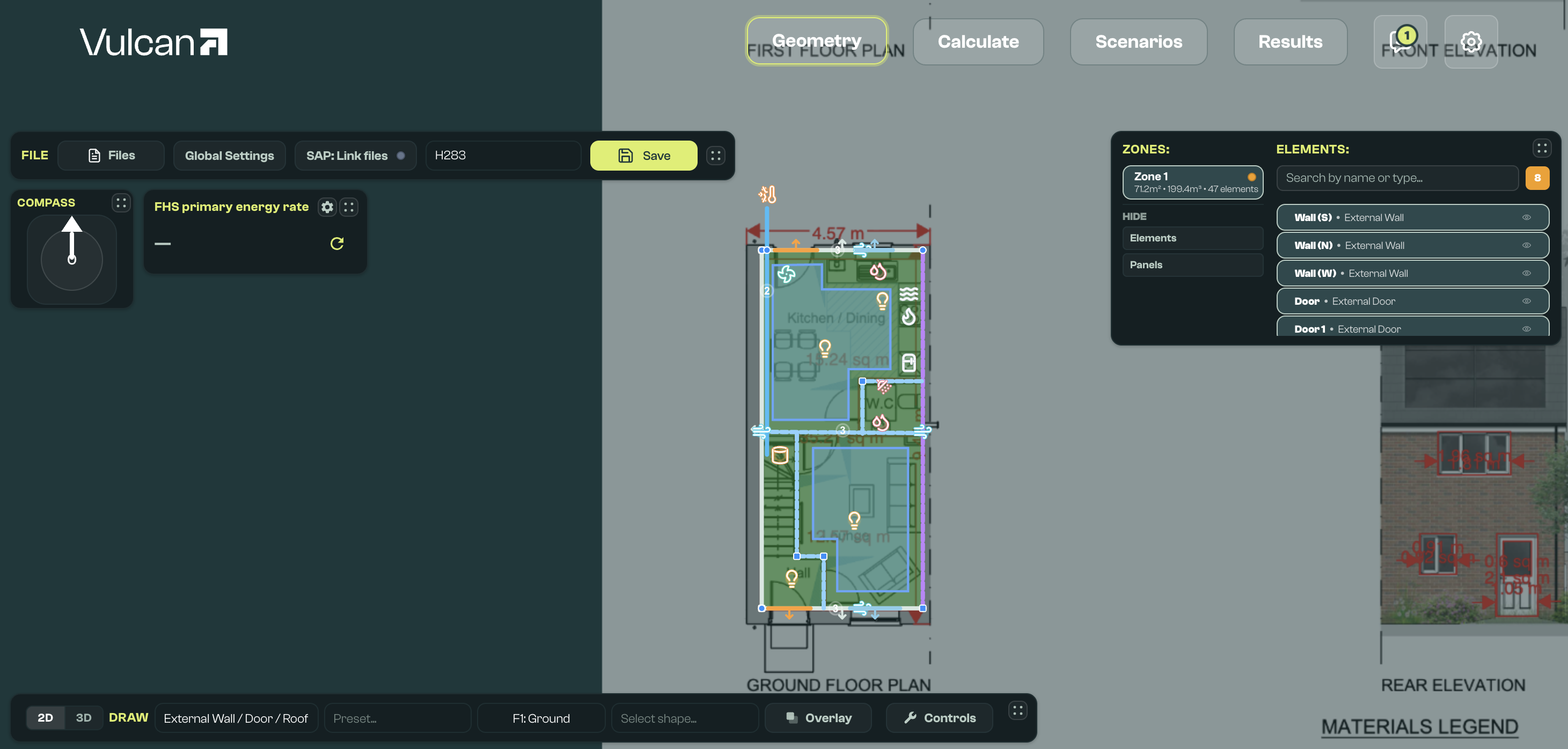
This data is saved into a CSV format 'geometry file', which is merged with a JSON format 'defaults file' when you click Save. The geometry file captures the minimal information needed to describe the geometry of a dwelling, and any differences from a default set of system and fabric properties. This helps minimise the inputs required for a HEM simulation.
Dwelling inputs can be created, edited, and saved with the following menus and panels. Most panels can be dragged to other parts of the canvas, collapsed, or hidden where controls provide that option.
| Menu or panel | Main purpose |
|---|---|
| File Bar | Open, name, save, group, and import model inputs. |
| Files dropdown | Search files, create a new model, and upload IFC files. |
| Projects and developments | Group models and manage development context. |
| Global Settings | Choose defaults files, set default assemblies, edit global values, and review values derived from the model. |
| Compass | Set the model orientation offset. |
| Draw toolbar | Choose 2D/3D mode, element type, preset, drawing shape, and drawing controls. |
| Floor picker | Choose the active floor, add or delete floors, and review floor base heights. |
| Thermal bridge proposer | Suggest and validate linear thermal bridge elements from the drawn geometry. |
| Overlay controls | Add, calibrate, move, or remove a plan image or PDF for tracing. |
| Canvas | Draw, select, move, and visually check elements and zones. |
| Editor | Edit a selected element, zone, or multi-element selection. |
| Zone editor | Review a zone and open Space Labeller for room or space footprints. |
| Viewer / Elements panel | Select elements and zones, filter validation issues, and show or hide elements or panels. |
| Quick sim | Run a fast preview calculation for the saved model. |
File Bar
The File Bar, typically at the top of the canvas, is used to open, name, and save input files, manage projects, edit global settings, and use SAP data to create or validate inputs.

Files dropdown
Interface to manage geometry input files (saved in the user workspace under input/base_models):
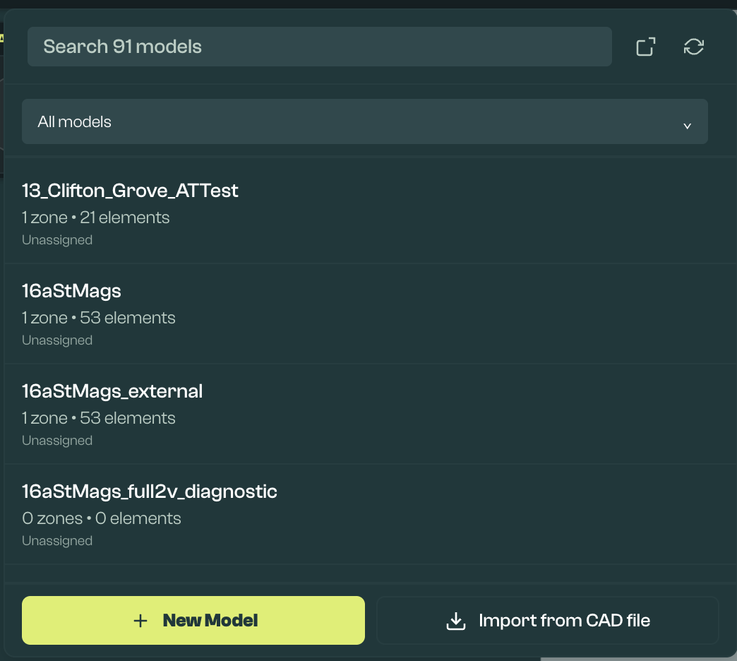
Open the file dropdown with the File button in the File Bar. Use it to:
- Search through all files by name.
- Open the workspace that contains the files.
- Refresh the view of files in this workspace, for example after adding new files.
- Delete a file. The delete action is visible when hovering over a file.
- New Model: Create a new file.
- Upload IFC: Upload IFC4 format files exported from CAD tools.
Projects and developments
The files dropdown also supports project grouping. Open the Files dropdown and use the project panel to create, select, rename, or delete projects.
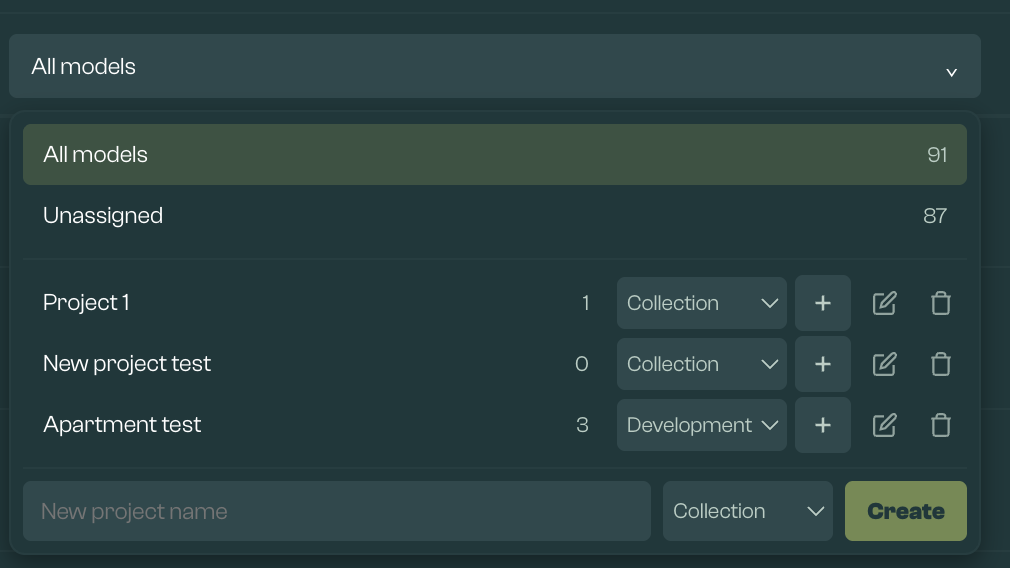
Projects are saved in the workspace in input/projects.json and can be used to filter the model list. Use the filter to show all files, unassigned files, or the files in a selected project.
There are two project types:
- Collection: A simple group of related models.
- Development: A group of related models where Vulcan can show context from sibling models.
A model must be saved before it can be added to or removed from a project. Deleting a project removes the grouping, not the model files.
When a Development is selected, other saved models in that Development can appear as context while editing. This is useful for terraces, apartment blocks, and plot groups where nearby dwellings affect shading or context.
Shared context shading can also be written back to sibling models when the model is saved. This helps keep repeated development context consistent. It updates the shared context items that Vulcan can match, rather than every element in every model.
If a new model is created while working in a selected Development, saving it can add it to that Development. This keeps the project filter and development context aligned with the saved model.
Project actions can also be used to start batch workflows for saved geometry models in the selected project.
File name field
Edit the name of the currently open file. The file must be renamed from the default name before it can be saved. Use a distinctive, searchable name.
Saving a file under a new name creates a new file and preserves historic saves. If a file already has that name, it is overwritten.
Save button
This button saves the current contents of the canvas into a CSV format geometry file. This can be found in your selected workspace folder, under input/base_models.
This is required before you can simulate the dwelling or submit it to ECaaS, and is important to ensure that updates made are not lost. The shortcut Ctrl + S can also be used to save.
Save status and build status are shown separately:
- Save success: The geometry CSV has been written to your workspace.
- Build errors: The CSV saved, but Vulcan could not create or validate the HEM input JSON. A Build Error button will show the issues to fix. These are usually missing or inconsistent fields rather than a failure to save your drawing.
- Save errors: The CSV itself could not be written. Clicking the warning symbol reveals more information about the cause.
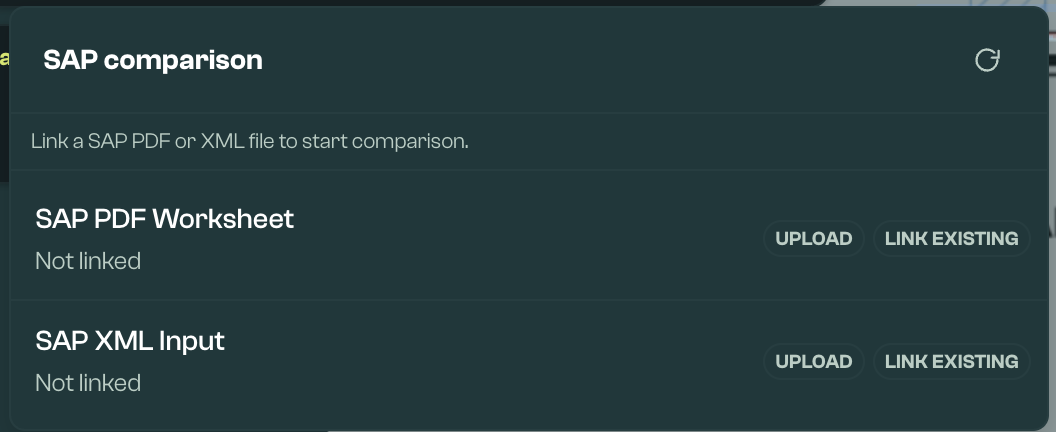
Import SAP Data
SAP data in PDF Worksheet or XML format can be imported with Upload to support creation and validation of HEM building elements within Vulcan. Once a SAP PDF or XML is used for one input file, it will be available to link to any other file with Link Existing.
Once a file is uploaded, the raw file (PDF or XML) or the extracted data (JSON) can be reviewed. The selected file can also be removed (Clear) or replaced by another file (Replace).
Vulcan stores SAP files and extracted data in the workspace. By default this is under input/sap/<model name>, unless the model has a specific SAP directory recorded. Extracted PDF and XML JSON files are cached with hash metadata so unchanged source files do not need to be re-extracted on every refresh.
Under Advanced, the pipeline to compare extracted data to the current HEM inputs is visible:
- Merged JSON represents the combination of the PDF and XML sources.
- Mapping JSON links the building elements in a SAP XML to the HEM input file. Manual mappings and blocked mappings are preserved when the comparison is refreshed.
- Diff JSON represents the difference between the current HEM input file and the SAP data described in the Merged JSON and linked by the Mapping JSON.
Validation provided by the SAP file is visible as a blue validation badge in the Elements Viewer, and as blue dots or chips within the Elements Editor. Validation can indicate that a HEM element contains a value inconsistent with the SAP files, or that a specific named element in the SAP file is missing from the HEM file. Missing elements can then be drawn or created with properties aligned to the SAP file.
If SAP differences look unexpected, check that the correct SAP file is linked, refresh the comparison after saving the model, and review the Mapping JSON for element names that could not be matched automatically. Duplicate or renamed HEM elements may need manual mapping before the diff reflects the intended comparison.
Global Settings
The Global Settings button opens the Global Settings menu. If there is a red validation dot on this button, there is likely an issue, for example a missing defaults file or required HEM value. This can be resolved within the menu.
Global Settings has two main tabs:
- Defaults: Choose the defaults file used when the geometry CSV is merged into a complete HEM JSON input. The selected defaults file is highlighted. From here, you can also edit or duplicate defaults files.
- Global values: Edit values that apply across the model.
Defaults tab
The Defaults tab controls the defaults file and default assemblies used when geometry is turned into a full HEM input.
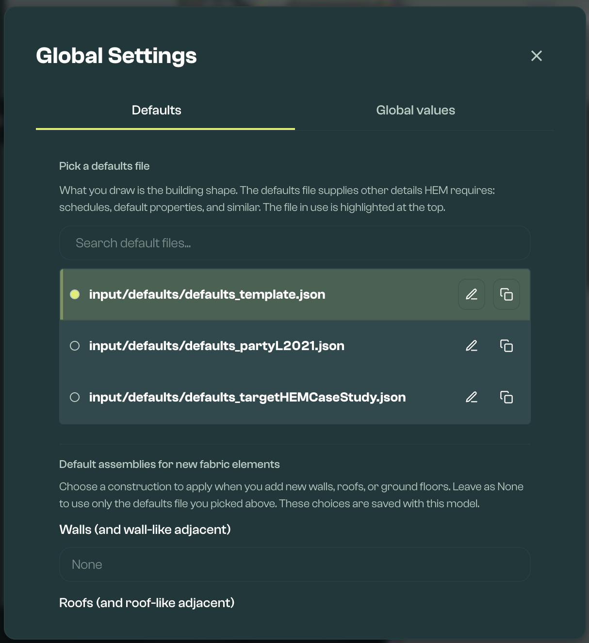
Default files are HEM input files in JSON format. They provide the foundation that geometry files merge into. A sample default file is part of the Sample Parameter Library, and stored in the user's workspace under input/defaults.
If using another input file as a default, pay attention to validation flags next to the file. These indicate missing data that may make it unsuitable as a general base for models.
Defaults files can be edited or duplicated from Global Settings when you need to adjust the assumptions used for new or merged models.
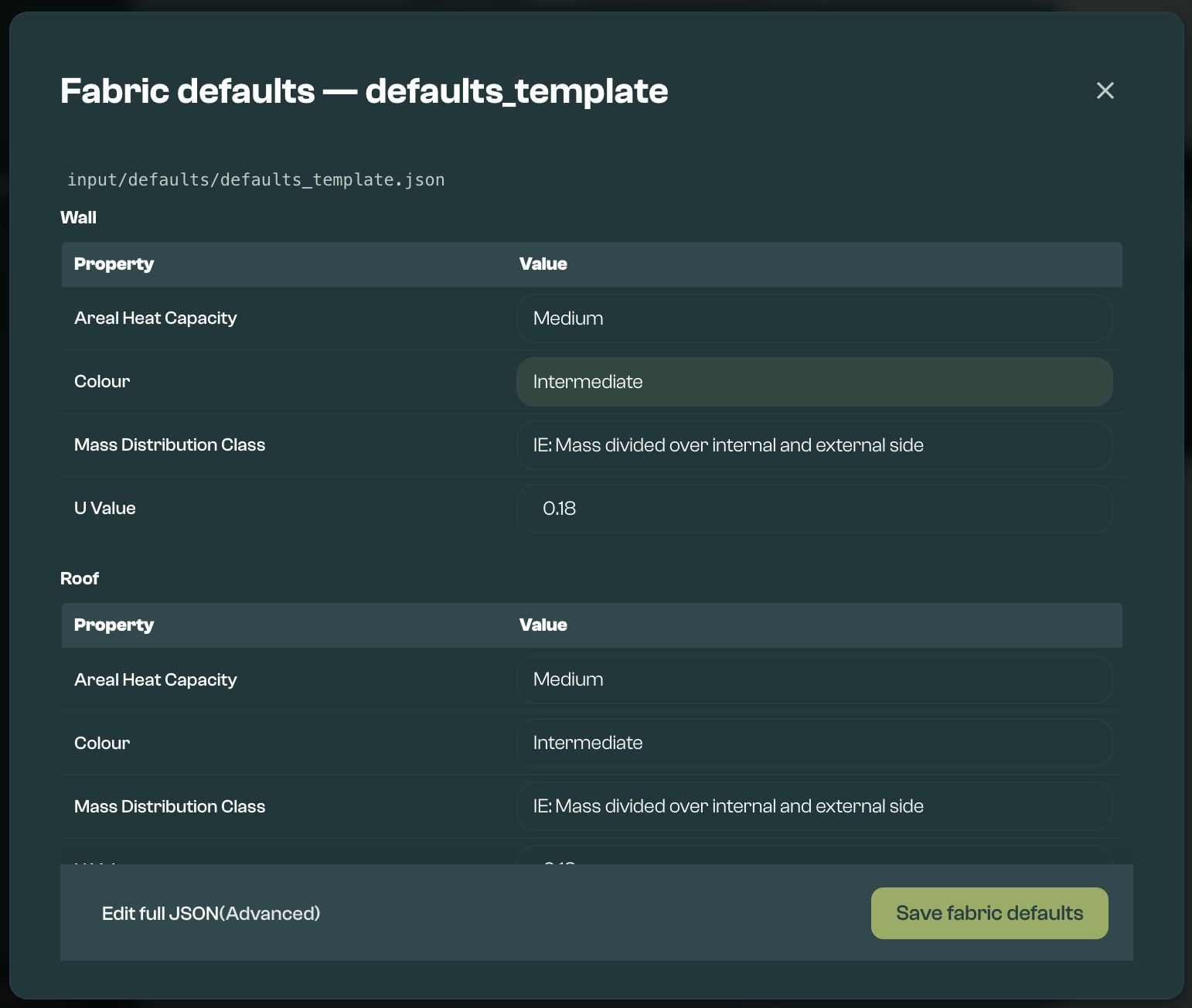
The Defaults tab also lets you choose default wall, roof, and ground-floor assemblies for newly drawn fabric elements. These defaults are saved with the model and used when new matching fabric elements are drawn. Changing a default assembly does not rewrite existing fabric elements, so review existing elements separately where needed.
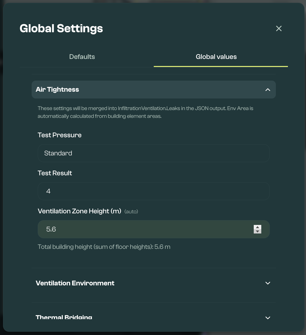
Global values tab
The Global values tab contains values that apply across the model.
The Global values tab includes:
- Dwelling Details: Shows compliance inputs such as Part G, room counts, hot-tapped rooms, ground floor area, heating control type, and related assumptions. Room counts should come from labelled spaces where possible, rather than being typed directly. Some other values are derived from the model and can be overridden where needed.
- Air Tightness: Records the test pressure and test result. Ventilation zone height and envelope area can be derived from the drawn geometry, with manual overrides where needed.
- Ventilation Environment: Records location settings that affect ventilation, including shield class, terrain class, altitude, ventilation zone base height, and noise nuisance.
- Thermal Bridging: Sets fallback heat loss and psi data used when individual thermal bridge elements are not provided or cannot be matched. This is where simplified or model-wide thermal bridge assumptions are set. Use the Draw toolbar for individual bridge proposal and validation.
Auto-updated values in Global Settings
Some Global Settings values can update from the model, so users do not need to maintain the same information in multiple places.
| Area | What can update | What to check |
|---|---|---|
| Space labels | Room counts can be synced from labelled spaces. Living area, rest-of-dwelling area, and treated floor area can also be derived from labelled spaces. | Refresh footprints after editing walls, then check room types. Use Use space labels where the room counts should match the labelled spaces. |
| Geometry dimensions | Ground-floor area, building length, and building width can be derived from the drawn model. | Check unusual shapes, split levels, and incomplete floors before calculation. |
| Airtightness and ventilation | Ventilation zone height, ventilation base height, and envelope area can be derived from drawn fabric and floor heights. | Check these values where storeys, adjacent spaces, or base heights are unusual. |
Manual overrides work slightly differently by field. Geometry-derived fields such as ground-floor area, building length, building width, ventilation height, and ventilation base height stay manually set until they are reset. Room-count fields can be typed manually, but if they differ from labelled spaces Vulcan marks them as a manual override and shows Use space labels to sync them back.
Evidence can be linked to fields in Global Settings where supporting evidence is needed.
For the main FHS compliance workflow, FHS validation is required. It checks the values that can be exported to the HEM:FHS wrapper.
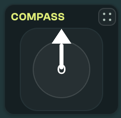
Compass
The Compass sets the global orientation, which applies an offset to the orientation value of all dwelling elements. Edit it by dragging the arrow, or by clicking the central number and typing the offset. Note that North = 0; East = 90; South = 180; West = 270.
Draw toolbar
The Draw toolbar is used to choose dwelling elements to draw, and how and where they are drawn. Drawn elements can be seen in the Viewer, and properties of selected elements edited in the Editor.

2D/3D toggle
This switches between 2D and 3D. Use 2D mode for drawing and editing geometry. Use 3D mode to visually check elevation and, where available, select, multi-select, and frame existing elements while reviewing the model. Some drawing and detailed editing actions still need to be done in 2D.
Element Selection
Choose which element to draw from the element selector:
- External Wall / Door / Roof
- External Window
- Ground Floor
- Internal Element, for internal walls, floors, and ceilings next to conditioned space
- Unheated Element, for walls, floors, or ceilings next to an unheated space, such as an unheated garage or stairwell
- Party Wall, for party walls only
- Thermal Bridge (Linear)
- Thermal Bridge (Point)
- Window Shading, which must be assigned to a window
- Lighting
- Ventilation Ductwork, which must be assigned to a mechanical ventilation unit
- Water Pipework
- Heating System Distribution
- Electric Appliance
- Hot Water Point
- External Shading
- Infiltration Vent, which can be assigned to a parent to inherit pitch and orientation
- Mechanical Ventilation
- Solar Panel
- Electric Battery
- System, including Product Characteristics Database product selection where available
Water Pipework and combustion appliances are not currently drawn when the model is being prepared for the FHS compliance path. Use systems/defaults where relevant, and check the validation messages for any missing inputs.
For ventilation, distinguish background ventilation from mechanical ventilation. Use Infiltration Vent for background vents that belong on a wall or window. Use Mechanical Ventilation for MEV or MVHR units, and Ventilation Ductwork for ducts that belong to a mechanical ventilation unit. For MVHR, FHS validation expects ductwork elements linked back to the MVHR unit. Part F ventilation checks use dwelling details, space labels, background vents, extract inputs, and mechanical ventilation inputs, so fix room labels and parent links before treating the warning as a system sizing issue.
Party floors and ceilings:
- Draw an Internal Element as a horizontal polygon, select it, then use the Party floor or Party ceiling checkbox in the Editor.
- Use Party Wall for party walls only, not floors or ceilings.
- When using the assembly calculator, Vulcan writes half-construction resistance and areal heat capacity, then recalculates U-value from that half construction.
- When typing advanced fields manually, enter half-construction values: U-value from the half build-up, half areal heat capacity, the matching mass class, and half construction R where construction R is used. See Fabric Calculators Reference for the detailed convention.
Thermal bridge proposer and validation
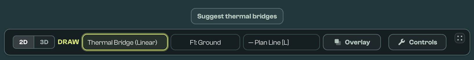
Vulcan can suggest likely thermal bridge elements from the drawn geometry. To open the proposer, choose Thermal Bridge (Linear) in the Draw toolbar, then click Suggest thermal bridges.
The proposer is deliberately geometry-based. It suggests linear Table 3.7 junctions only where the drawn elements provide enough information for the junction location and length:
| Geometry Vulcan looks for | Suggested junctions and choices |
|---|---|
| Vertical wall windows and external doors drawn as straight wall openings | Lintel, sill, and jamb rows. Defaults are E1, E3, and E4. Use the junction dropdown to choose the correct opening code from E1-E4, for example E2 for other lintels. If the opening foot is at a floor slab, Vulcan suggests the wall-floor row instead of a separate sill. |
| Roof windows and rooflights with a non-vertical pitch | R1 head, R2 sill, two R3 jambs, and an R11 kerb/upstand row along the lower edge. Use R2 for a sill detail or R11 for a kerb/upstand; do not keep both for the same physical line unless there are genuinely separate details. |
| External walls linked to ground or intermediate floor slabs | Continuous E5 ground wall-floor rows and E6 intermediate wall-floor rows. Vulcan subtracts door/window foot spans already suggested on the same wall line. Ground rows can be changed to E19 where the inverted ground-floor junction is the right detail. |
| Ground elements with a basement floor type | E22 along each edge of a heated or unheated basement floor polygon. |
| External wall plan corners | E16 normal corners and E17 re-entrant/inverted corners. Endpoints very close together are merged, but T-junctions, loose wall stubs, internal walls, and pitched/roof-like walls are not treated as external-corner rows. |
| Flat roof deck edges | E14 flat roof by default; choose E15 where the same line is a flat roof with parapet. |
| Sloped roof edges | E10/E11 eaves on the first or drawn low edge, E12/E13 gables on suitable perpendicular plan edges, and R4 ridge rows on warm roof polygons where a non-first edge is nearly parallel to the eaves. R5 is available in the dropdown on emitted ridge rows. Cold unheated pitched roofs use the ceiling-level E10/E12 eaves/gable codes and do not emit ridge rows. |
| Sloped roof edges meeting adjacent vertical walls or room-in-roof walls | R8/R9 where the roof edge and adjacent wall line are plan-coincident and have enough vertical overlap. Warm roofs default to R8; cold unheated pitched roofs default to R9. |
| Dormer walls and dormer roof planes linked to a host roof | R8/R9 for dormer wall to host roof lines, and R10 for warm dormer roof edges tying back into a warm host roof where the edge is not already an eaves, gable, ridge, or roof-window edge. |
| Party floors, party walls, and adjacent unheated floors | E7 for a party floor or party ceiling meeting an external wall; E18 for a vertical party wall meeting an external wall; P1/P6 for party wall to ground floor; P2/P3 for party wall to intermediate conditioned floor; P4/P5 for party wall to pitched roof; P4 for party wall to flat roof; E20/E21 for an unheated exposed floor meeting an external wall. Use the dropdown to choose the normal/inverted or ceiling/rafter variant where the default does not match the evidence. |
The tool has two views: Suggested new and Inventory. Suggested new shows bridge rows Vulcan can add from the current geometry. Inventory reviews existing linear thermal bridges as problematic, manual-only, or validated.

The table above shows where the junction dropdown offers related alternatives on a suggested row rather than creating a separate default row. Use those alternatives when they better match the construction and evidence.
Vulcan also lists Table 3.7 codes that are outside the current auto-suggest set, so users can decide whether evidence supports a manual bridge. The proposer does not create automatic rows for E8, E9, or E23 balcony junctions, E24 inverted eaves, E25 staggered party walls, or R6/R7 flat ceiling junctions. Add these manually where they apply.
Before the rows are shown, Vulcan de-duplicates substantially overlapping suggestions. It also treats a suggestion as a duplicate when an existing thermal bridge has the same junction type and a midpoint within about 0.12 m, so expected rows may be absent because an existing or higher-precedence row already covers the same physical line. Check Inventory when a junction you expected is not shown under Suggested new.
Use the proposer as a review workflow: propose likely junctions, check the list, apply the suggestions you want to use, then validate the result. The suggestions should be reviewed before they are applied to the model.
Thermal bridge validation checks the drawn thermal bridge elements against the surrounding geometry. It can flag missing links, overlaps, duplicated junctions, or junctions that do not appear to match the nearby modelled elements.
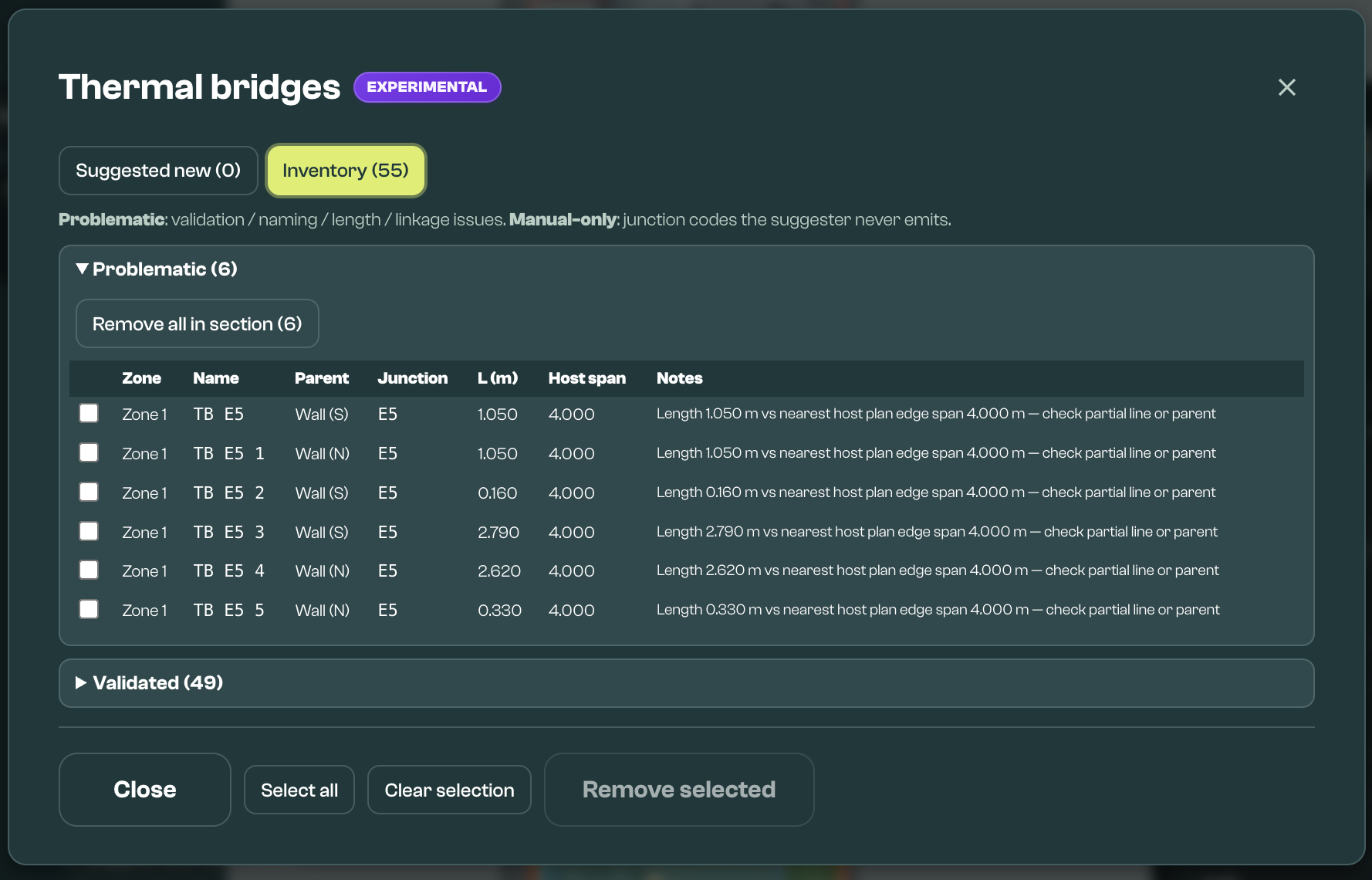
Read the Inventory buckets as follows:
- Problematic: The bridge has a validation, naming, length, linkage, or duplicate/overlap issue that should be checked.
- Manual-only: The bridge's junction code is outside the current auto-suggest set. This does not mean the bridge is wrong, but it should be justified from evidence or professional judgement.
- Validated: The bridge has a recognised junction code and the current geometry/linkage checks do not find a problem.
The proposer is based on the drawn geometry. It may not suggest junctions that are not clear from the drawing, are not snapped cleanly, span unusual floor or roof conditions, use details that are not represented by the drawn elements, depend on a product-specific construction, or need evidence outside the model. Add or adjust those thermal bridges using the evidence and psi values you intend to rely on.
Suggested bridges use the configured thermal-bridging value for the selected junction where Vulcan has one, falling back to the default or Table 3.7 value where needed. To change the model-wide or fallback psi values Vulcan uses, open Global Settings > Global values > Thermal Bridging. Where enabled, detailed bridge value sources may also be available there. If the dwelling uses an assessed psi value, proprietary detail, Accredited Construction Detail, or another evidence-backed value, check the created thermal bridge element still has the correct junction type and linear thermal transmittance before relying on the result.
Where more than one suggested bridge could describe the same physical junction, choose the one that matches the construction and evidence. Avoid keeping duplicated or overlapping bridge elements for the same junction unless there is a clear reason.
These messages are guidance for checking the model and should be reviewed before calculation. If the model uses simplified thermal bridging, individual thermal bridge elements may not be needed for a first model.
Preset
Use Preset to select a saved element of that type. Presets can be saved from existing elements using the Element Editor menu.
Floor picker and floor heights
Use the floor picker in the Draw toolbar to choose the active floor before drawing. Floors use FHS conventions: F1 is the ground floor, F2 is the floor above, and F0 is the first basement floor.
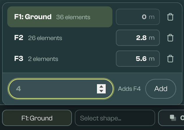
From the floor picker you can:
- switch the active floor
- add a floor by typing the FHS floor number
- delete a floor, which also deletes elements on that floor
- review or edit the floor base height
Floor base height is the elevation of that floor in metres. F1 is fixed at 0 m. Upper floors are normally derived by adding the effective heights of the floors below. Basement floors use negative base heights.
Vulcan normally derives storey height from drawn vertical wall heights. If a floor has no own vertical walls, it can inherit the nearest lower wall height. If no wall height is available, the stored floor height is used. Typing a base height creates a manual override. If the typed value matches the wall-derived height, the override is cleared. A warning icon can appear when a manual floor height no longer matches the walls; click it to reset to the wall-derived value.
For opaque and transparent elements, base_height stores the element's absolute height above ground. This means an upper-floor window can have a base_height greater than its sill height above that floor. When an element is moved between floors, Vulcan moves its vertices to the new floor and tries to preserve its height above the old floor. For example, a window with a 0.9 m sill stays 0.9 m above the new floor. Related window heights update with it.
Changing a floor height can update stored base heights on affected elements so they keep the same offset from their floor. Elements without an authored base height may not change. Validation can warn when a base_height falls below the selected floor slab or above the storey ceiling. Thermal bridge linear elements are different: their floor assignment changes, but their physical line heights are preserved.
Shape Selection
Choose how the element is represented with a top-down view. After choosing a Shape, the next click on the canvas will start drawing. Shapes can also be quickly selected by using the keyboard shortcut shown, or de-selected with Escape. The Shapes available will depend on the Element Selection.
- Line: A vertical panel. The arrow indicates the externally facing surface of the element. Shortcut:
[ L ]. - Polygon: A flat plane. Click the original point to close. Shortcut:
[ P ]. - Slope: An angled plane. The first two points are the lowest edge of the slope, and the arrow indicates the externally facing direction of this edge. Shortcut:
[ J ]. - Room: Vertical panels enclosing a polygon. The arrow indicates the externally facing surface of the room walls. Shortcut:
[ K ]. - Orthogonal Room: A rectangular room. Click and drag to place, then tweak dimensions in the post-room-creation menu. Shortcut:
[ Q ]. - Dormer: Add dormer geometry to a roof where available, then configure the dormer as hip, gable, or shed. Only available for External Wall / Door / Roof.
- Thermal bridge line modes: Thermal bridges can be drawn as plan, vertical, or sloped lines.
- Point: Click to place. Shortcut:
[ O ].
Hold Shift while drawing to force orthogonal snapping. Hold Alt/Option while placing repeated elements, especially lines, if you want to keep drawing the same shape.
Overlay
Use Overlay controls to select an overlay file (PNG, JPEG, or PDF) that can be traced over in the canvas. This can make it faster to create inputs from a floor plan.

When a model has more than one floor, check the selected floor before choosing or calibrating an overlay. Each floor can remember its own overlay position, which helps align plan images so floors can be drawn on top of each other. Where available, moving an overlay customises the active floor relative to the inherited position, resetting returns to the inherited position, and deleting removes the overlay from every floor.
- Select overlay image: Choose an image as an overlay. Overlay files are saved in your workspace. PDF sources are retained separately and the selected page is converted to a PNG overlay. Where the model is linked to a lodgement, Vulcan can also attach overlay files as internal QA evidence.
- Calibrate image: Place two points onto the canvas, then define the distance between them. This is automatically prompted on loading a new image. Overlays can be re-calibrated at any time.
- Replace overlay image: Choose another image as an overlay.
- Remove overlay image: Remove the currently selected overlay image.
- Move image: Drag the selected image around the canvas.
- Change opacity: Change the visual transparency of the image.
Controls
The canvas controls panel contains shortcuts and drawing toggles:
Mouse and Keyboard Controls: Reiterates controls above and provides other options:
[ S ]when hovering over the edge of a polygon to add a vertex[ + ]or[ - ]to zoom in or out, also supported by touchpad[ Ctrl + S ]to save the current inputs[ Ctrl + Z ]to undo the last draw[ Ctrl + Y ]or[ Ctrl + Shift + Z ]to redo[ Delete ]to delete an element or selection[ Escape ]to clear the drawing tool or current selection- Click and drag to select multiple elements to edit, duplicate, move, or delete as a group
Snap and Label options: Controls when drawn or adjusted elements snap to a grid, nearby corners, nearby edges, or potential parent elements. Hold Shift while drawing to force orthogonal snapping. Snapped vertices can stay joined when moved. Use these controls when walls should meet cleanly, openings should sit on a host wall, or polygon corners should stay connected.
Canvas
Use the canvas to view elements, select them for editing, and move around the model. Panels can be dragged around the canvas, collapsed, or hidden where controls provide that option, so you can create more drawing space.
Editor
Single element editor
Use this editor to edit one element at a time.
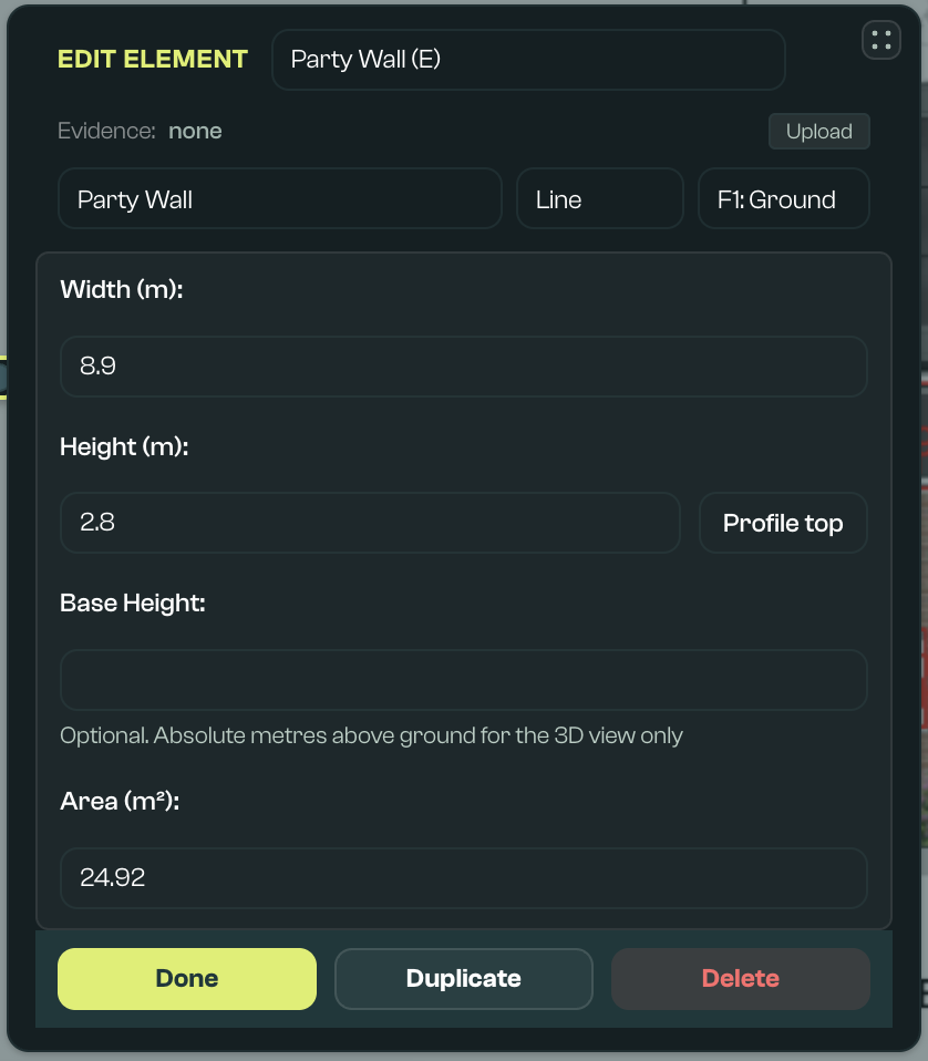
- Name: A human-readable name that has no impact on its properties.
- Type: Controls element properties. Element shape is constrained by type.
- Floor: Change the element to another floor by inputting directly, or select from available floors.
- Preset: Select a saved element preset or save the current element as a reusable preset where available. This is useful for repeated walls, windows, and other elements that share the same assumptions.
- Assembly picker: For fabric elements, choose a saved assembly or build up layers from materials, cavities, and repeating bridges. Vulcan uses this to estimate fabric values such as U-value, construction resistance, and thermal mass. You can apply the result to the element and keep an auditable record of the assumptions.
- Ground U-value tools: For ground floors, Vulcan can help estimate U-value using the element area and perimeter, wall thickness, floor type, and relevant insulation or ventilation inputs. Suspended floors can also use underfloor insulation resistance and ventilation assumptions. See Fabric Calculators Reference for more detail on these calculations.
- Thermal resistance of unheated space tool: For elements adjacent to an unheated space, Vulcan can help calculate the extra thermal resistance of that space (
R_u) and write it back to the element. Use this where a wall, floor, or roof separates the heated dwelling from an unheated garage, loft, stairwell, or similar space. Pitched roofs can also be marked as unheated where the internal heat-transfer surface should be treated differently from the external roof pitch. - System and PCDB inputs: System elements can use product data from the Product Characteristics Database where available. This helps populate system inputs from a selected product, but users should still check that the selected product and linked system assumptions match the dwelling. For heat-pump PCDB products, Vulcan currently marks the mapping as ECaaS-only: it is intended for the ECaaS FHS profile and is not runnable in standard local FHS mode. For standard local runs, use a System preset or a complete heat-pump system definition.
- Validation flags: "Critical" (red) errors prevent HEM runs. "Warning" (orange) errors may indicate gaps or inaccuracies. Note flags are horizontally scrollable.
- Standard fields: Shown below the element. These are usually what is required to model the element in HEM's core methodology. Hovering over the label provides guidance on each field.
- Advanced fields: Less commonly available fields the user can optionally set. From Defaults means the value is set by the defaults file unless overridden for this element. No Defaults, Schema Shown means the typical form of the field is shown from the schema; if a value is provided, it will be added to the HEM JSON for this element.
- Duplicate: Creates a copy of that element.
- Delete: Deletes this element after user confirmation.
Zone editor
The Zone editor is used to review a zone and manage the space labels within it.
Select a zone from the Viewer to open the Zone editor. A single zone is created by default when elements are drawn. Additional zones can be added where needed, but may be merged in compliance assessments.
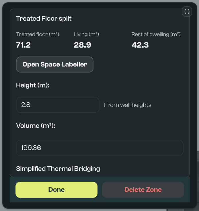
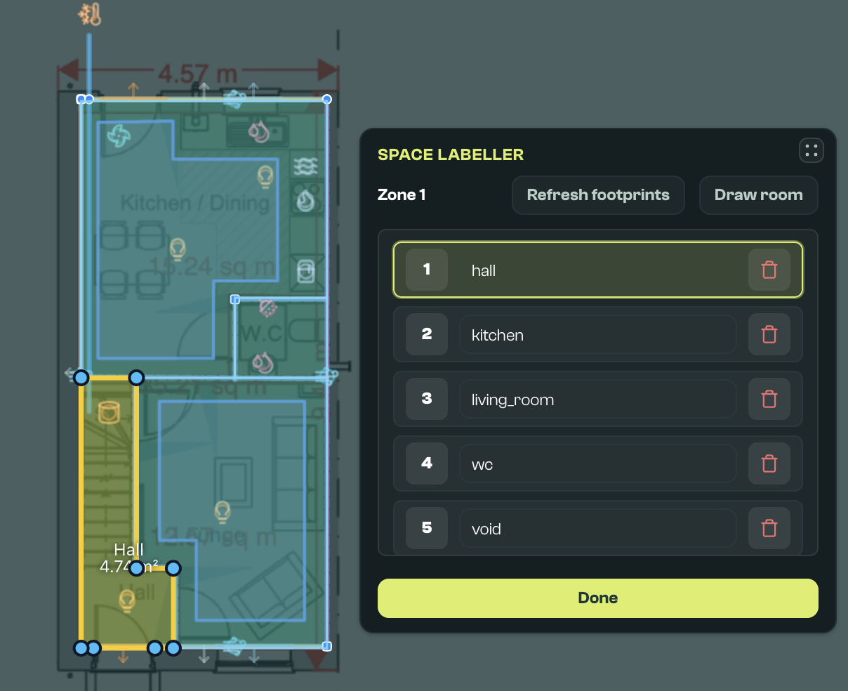
Open Space Labeller from the Zone editor, or from the space assignments link in Global Settings where room counts are shown. Space Labeller is used to mark room or space footprints within a zone.
Vulcan can infer space footprints from closed wall loops. Use Refresh footprints after editing walls. Use Draw room when a space needs to be added manually.
Each space should be assigned a room type, such as bedroom, living room, kitchen, bathroom, WC, utility, hall, circulation, other habitable, void, or other. Room types are used to derive room counts and can help set treated floor area, living area, and rest-of-dwelling area.
Room types feed simple compliance counts. Bedrooms count as bedrooms and habitable rooms. Living rooms count as habitable rooms and living area. Kitchens, bathrooms, WCs, and utility rooms feed wet-room, hot-water, or sanitary counts where relevant. Halls, circulation, voids, and other spaces can still contribute to floor area. Void labels and unknown room types do not add room counts; unknown room types show a warning so they can be checked.
Global Settings shows whether each room-count field is from space labels or a manual override. Use Use space labels to sync one field, or all room counts, back to the labelled footprints.
Space labels can show warnings if a space is not labelled, has an unknown room type, overlaps another space, or extends outside the floor area. Fix the room type, redraw the space, or refresh footprints after changing walls. Space labels are saved in the geometry CSV in a Space Labels section.
Object interactions and parenting
Some objects should be linked to a parent element. This includes openings linked to a host wall or roof, shading linked to a window, vents and hosted mechanical ventilation fans linked to a wall or window, ductwork linked to its mechanical ventilation unit, and roof-hosted objects such as solar panels.
Set or review parent links in the Editor after selecting the object. For example:
- Windows and doors should normally be linked to their host wall or roof.
- Window shading should be linked to the window it shades.
- Infiltration vents can be linked to a wall or window so pitch and orientation stay consistent.
- Mechanical ventilation can be linked to a wall or window for hosted MEV fan types so placement, pitch, and orientation stay consistent. MVHR ductwork should be linked to the mechanical ventilation unit it belongs to.
- Solar panels should normally be linked to the roof plane they sit on.
Parent links help Vulcan infer placement, pitch, orientation, and validation checks for supported child types. After moving or renaming a host, review linked child elements; some links may need to be reset. If a parent is missing or a vertex is not snapped, Vulcan may show a warning in the editor, viewer, or canvas label.
Multiple element editor
Use this editor to edit multiple elements at once. It is only visible when multiple elements are selected. Use Shift+Click to select each element in the canvas or Element Viewer, or click and drag to marquee select.
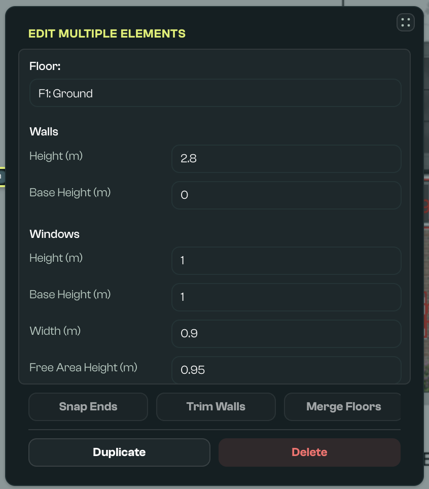
- Floor: Updates the floor for all selected elements.
- Batch properties: Updates specific properties for all selected elements. The current value of this property for selected elements, and the number of elements with this value, is shown below the inputs. Some property controls apply as soon as they are changed; others use Apply. Check the selected values after bulk editing, especially when the selected elements started with different values.
- Snap: Extends linear elements so they snap to nearby vertices. The snap distance is indicated in metres in the Snap input field to the right of the button.
- Trim: Removes any part of linear elements that extend beyond another linear element. The trim applies to the portion of the element furthest from the centre.
- Right align: Adjusts the angle of linear elements to orthogonal angles, if they are within range. This range is indicated in the Angle input field to the right of the button.
- Apply: Applies batch property changes. This is not required for transforms such as Snap, Trim, Align, Duplicate, or Delete.
- Duplicate: Creates a duplicate of this group of elements.
- Delete: Deletes this group of elements after user confirmation.
Viewer / Elements panel
Shows all elements and zones in an input file. This panel can be moved, resized by dragging edges, or reset to its original state by double clicking the same handle.
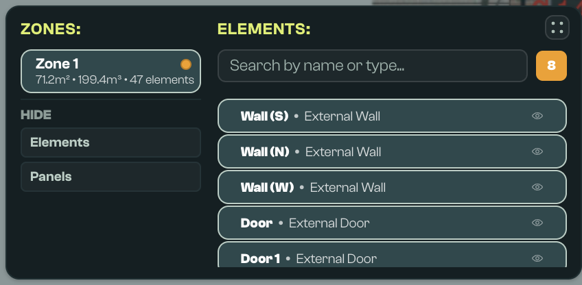
- Show/hide elements: In the Viewer/Elements panel, use Hide > Elements to hide thermal bridges, onsite generation, ductwork, pipework, sloped roofs, vents, or individual element pills. Hidden elements are not interactive on the canvas, but they remain in the model and saved CSV. Individual hidden element choices are saved locally for that model.
- Show/hide panels: In the Viewer/Elements panel, use Hide > Panels to hide or show the File, Compass, Draw toolbar, and Quick sim panels. This changes the current workspace view only and can be used to make more drawing space.
Element and Zone pills
Click an element or zone pill to select and edit it in the Element Editor. Double click to centre it on screen. A single zone is created by default when elements are drawn; additional zones can be added, but may be merged in compliance assessments.
Search bar
Search elements by name or type.
Validation badges
Badges displayed next to the search bar indicate validation issues:
- Warning: Orange validation dots or badges. These will not block a run.
- Critical: Red validation dots or badges. These will prevent a HEM core run.
- SAP differences: Blue validation dots or badges. These indicate a difference to SAP inputs.
Validation is also visible inside the Element Editor when an individual element is selected, and in an element's label on the canvas. Clicking on a validation badge in the Element Viewer filters to elements with that issue type.
Note that when FHS Compliance validation is active in Global Settings, gaps against the FHS schema will be Critical.
Part F ventilation checks may also appear in validation. These checks use dwelling details, space labels, background vents, extract inputs, and mechanical ventilation inputs to highlight missing or insufficient ventilation. Start by checking room labels, then check the relevant vent or mechanical ventilation element.
Quick sim / quick solve
The Quick sim panel can run a preview calculation for the current saved model and show headline results such as FHS primary energy rate or annual solar generation.

Use it as a fast sense-check while building the model. Save the model before running Quick solve, then refresh the preview after making further saved changes.
Quick solve uses the batch workflow in the background and creates a preview run for the saved model. Weather can be selected in the panel. The default preview weather is RAF_Bedford_01 where no other weather file is selected.
Use the Calculate section for ECaaS submissions and the Scenarios section for full scenario modelling. Quick solve is intended for quick checks during Geometry work.
CSV file format for HEM inputs
Most visual inputs in the Geometry screen are saved as CSV files in input/base_models in the user's workspace. This folder can be opened from the File Bar file selection dropdown. The CSV format can be reviewed in spreadsheet tools and integrated with local workflows. When saved, it is merged into a HEM JSON file using the selected defaults file.
For day-to-day use, most users should edit geometry through the canvas and use the CSV file as an auditable record of the model.
For integrations or spreadsheet workflows, see the Geometry CSV contract.